Some notes
about commercial HF amateur radio transceivers for CW/SSB Contest
operations focusing on a relevant parameter of third order CLOSE-IN IMD DR (a
two RF tones test)
Take note, from ARRL, RSGB, or personal laboratory test report data of HF
Transceivers, about close in IMD figures DR (two tones spaced
apart between 2 to 20 Khz, that fall just inside the first roofing filter in
most commercial upconversion transceivers that, until now, make use of wide
first IF "roofing" filters). From 20 khz to 50
Khz usually they are better.
Some relevant links for laboratory reports on Amateur Radio Transceivers:
ARRL (members only) (ARRL members login only, there is a big document
available about Test Procedures)
available some expanded test report and see QST Magazine Product Review, on
paper or CD ROM from ARRL.
RSGB (members only) (RSGB members login only) and on paper or CD in RADCOM (RSGB) Magazine
W8JI, Tom Rauch and Receiver Tests sorted by IM3
Sherwood Engineering Rob Sherwood NC0B and Receiver Performance White Paper (I suggest this reading)
Elecraft comparison charts (test data from ARRL)
Some data taken from Peter Hart G3SJX test reports presented in RADCOM (RSGB)
Magazine Oct-2000 and June-2002. Close-in
IMD DR or IIP3 (dBm) e IMD3DR (dB) with two RF tone test,
spaced closely from 3 Khz to 50 Khz of 2 well known transceivers
(7Mhz, preampl. OFF):
|
TRX |
freq offset |
3Khz |
5Khz |
7Khz |
10Khz |
15Khz |
20Khz |
30Khz |
40Khz |
50Khz |
|
FT1000MP MARK V |
IIP3 |
-9 |
-14 |
-12 |
-5 |
+10 |
+18 |
+18 |
+18 |
+18 |
|
IMDDR |
77 |
73 |
75 |
79 |
89 |
95 |
95 |
95 |
95 |
|
|
IC756PROII |
IP3 |
-19 |
-16 |
-12 |
-1 |
+10 |
+22 |
+20 |
+20 |
+20 |
|
IMDDR |
71 |
73 |
76 |
83 |
91 |
99 |
98 |
98 |
98 |
Analysing RSGB, Peter Hart
G3SJX test report of a modern rig as IC756PROIII
from a critical “contester” crowded in-band signals point of view,
it appears a modest or not at all improvement over IC756PROII, in this CLOSE-IN
IMD behaviour area, until there will be a mode switchable sharper first roofing
filter. Receivers with sharper and mode related first IF filters are
potentially better in this Close-In IMD area. Even modified up conversion
rigs with original broad roofing filters end-up to be improved with a sharper
roofing filter placed inside. This is a nice experimental amateur
radio exercise seeking for any improvements.
Here there are some recent examples officially documented by ARRL and RSGB test report:
Some data resumed by QST, RADCOM for comparison about CLOSE-IN IMD:
ARRL laboratory, February 2005 QST, tested Inrad roofing filter mod inside an FT1000MP and Mark V two tone IMD DYNAMIC RANGE (14 Mhz, pre off) for:
|
TRX |
offset fre |
2Khz |
5Khz |
20Khz |
|
FT1000MP MARK V |
INRAD |
79 | 89 (*) | 93 |
|
without |
69 |
76 |
88 |
|
|
FT1000MP |
INRAD |
71 | 90 (*) | 100 |
|
without |
69 | 76 | 94 |
(*) measurement is reported to be noise limited at that value)
Also Peter Hart, G3SJX in January 2005 Radcom (RSGB magazine) (FT1000MP, 14 Mhz, CW 500 Hz, preamp OFF)
|
TRX |
offset |
3Khz |
5Khz |
7Khz |
10Khz | 15Khz | 20Khz |
|
FT1000MP
|
INRAD |
80 | 84 | 90 | 96 | 98 | 99 |
|
without |
74 |
76 |
81 |
85 | 98 | 99 |
(Inrad roofing filter is supposed to be around 4880 Hz wide since AM position
bandwidth has been measured by Peter Hart to be narrowed from 7 Khz to 4.880 Hz
- See INRAD web site and the pdf document
"a few words about Roofing Filters) which contains the following grafics
about INRAD 70.455 MHz first IF roofing filter mods for FT1000MP and
FT1000MP-MARK V and FIELD version Yaesu TRX:
Inrad 70.455MHz Roofing Filter:
If you look carefully to Ten Tec ORION close in IMD data (3 Khz to 20 Khz 2 tone test) from ARRL QST report
it appears that, in this area, it really tops every other rig now available (FTDX9000 not tested yet) and it has also a much better LO Synthesiser Phase Noise which really tops almost all other rigs and a sharper ultimate bandwidth is achievable, see bandwidth figures at attenuations below 60 dB.
Anyway a nice rig as IC756PROIII has so many features that it looks really a desirable rig especially now with the improvements released in MK III (really missing only the IC7800 switchable sharper first Roofing filter), so I suggest to get and read the complete test report in RSGB or ARRL magazines and final choices are personal and you should always listen to a rig personally to satisfy your needs and tastes.
Third order IMD DR with two RF tone at antenna input is mainly a FRONT-END (early input RX stages) test and
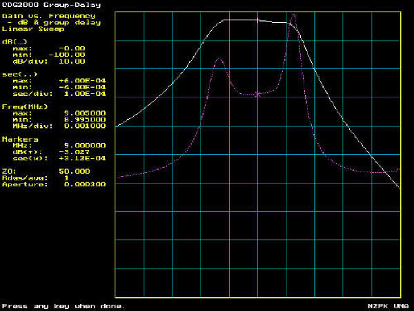
stresses all stages before the main sharp IF selectivity, with a close in imd test also the roofing filter, and it depends a lot to how sharp is selectivy in the early stages and to the linearity of the components (also passive one like inductors in front end filters can contribute to deteriorate or improve IMD immunity, even the roofing filter should be well implemented, see the larger coils used in IC756PROIII or coil selection in CDG2000 home-brew transceiver and IMD test report by G3SBI in Radcom June-Dec 2002). The CDG2000 9Mhz Roofing Filter is very much interesting. It basically a four pole, 4 quartz, for the in series 9 MHz IF signal but in parallel with others 4 quartz with an input and output splitter
so improving 3rd order in band IMD, and it provides also a good 50 Ohm match to the mixer - diplexer. Here is our duplicated unit and how it performs, tests are performed with a Vector Network Analyser VNA by N2PK with the professional help of its builder Eraldo, I4SBX.
|
CDG2000 9MHz Roofing Filter by I4FAF and IK4AUY
|
 |
 |
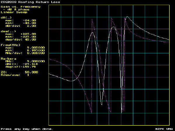 |
| In the above Return Loss picture you must add 12 dB to take in account
the measurement head system loss so max Return Loss is -12dB and minimum -32, that means VSWR is better than 1.5:1 a very good match to 50 Ohm for a quartz filter input and output splitters work well. |
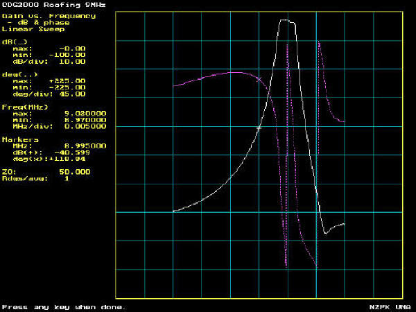 |
| CDG2000 9MHz Roofing Filter by I4FAF and IK4AUY 50KHz total Span or 5KHz per division |
IN-BAND AUDIO IMD
To get an idea about the receiver quality delivered to our ears, in good phones, it is interesting to see what happens in the following inside RX stages like IF Amplifiers, AGC, Detector and Audio. In the ARRL Expanded tests Report you can often find a two tone IN-BAND IMD test in which the 2 RF signals are applied at the RX antenna input at very close spacing for examples 200 Hz apart and the unwanted IMD products at base band audio frequency should be attenuated as much as possible (to say an higher absolute value in dB is better).
If the IF AMPLIFIER chain is contributing to the inband IMD more than the Detector or the Audio chain the IMD has
seen at audio is the poorest
of the poorer stage that contributes to it.
Audio quality is
also affected by frequency bandwidth response so it is worthwhile to
measure it.
last update 02.05.2005